GitBucket
Challenge 9: "Clock Spy"
You’ve uncovered a high-security vault guarded by a keypad that requires a 5-digit PIN. When the PIN is entered and the OK button pressed, the system checks the password internally.
Your task is to perform a timing side-channel attack to recover the PIN as quickly and efficiently as possible. But beware — the PIN changes every time the device reboots, adding an extra layer of complexity to your attack.
Disclaimer:
Normally, side-channel attacks require expensive equipment such as oscilloscopes and specialized tooling like a ChipWhisperer. However, we have intentionally added specific delays so these attacks can be performed using a very affordable logic analyzer.
Your mission is clear:
- Observe and measure timing variations during the PIN verification process.
- Use side-channel analysis techniques to deduce each digit of the PIN.
- Recover the correct 5-digit PIN before the device resets.
- Retrieve the flag via UART at 9600 baud rate.
Setup
Notes
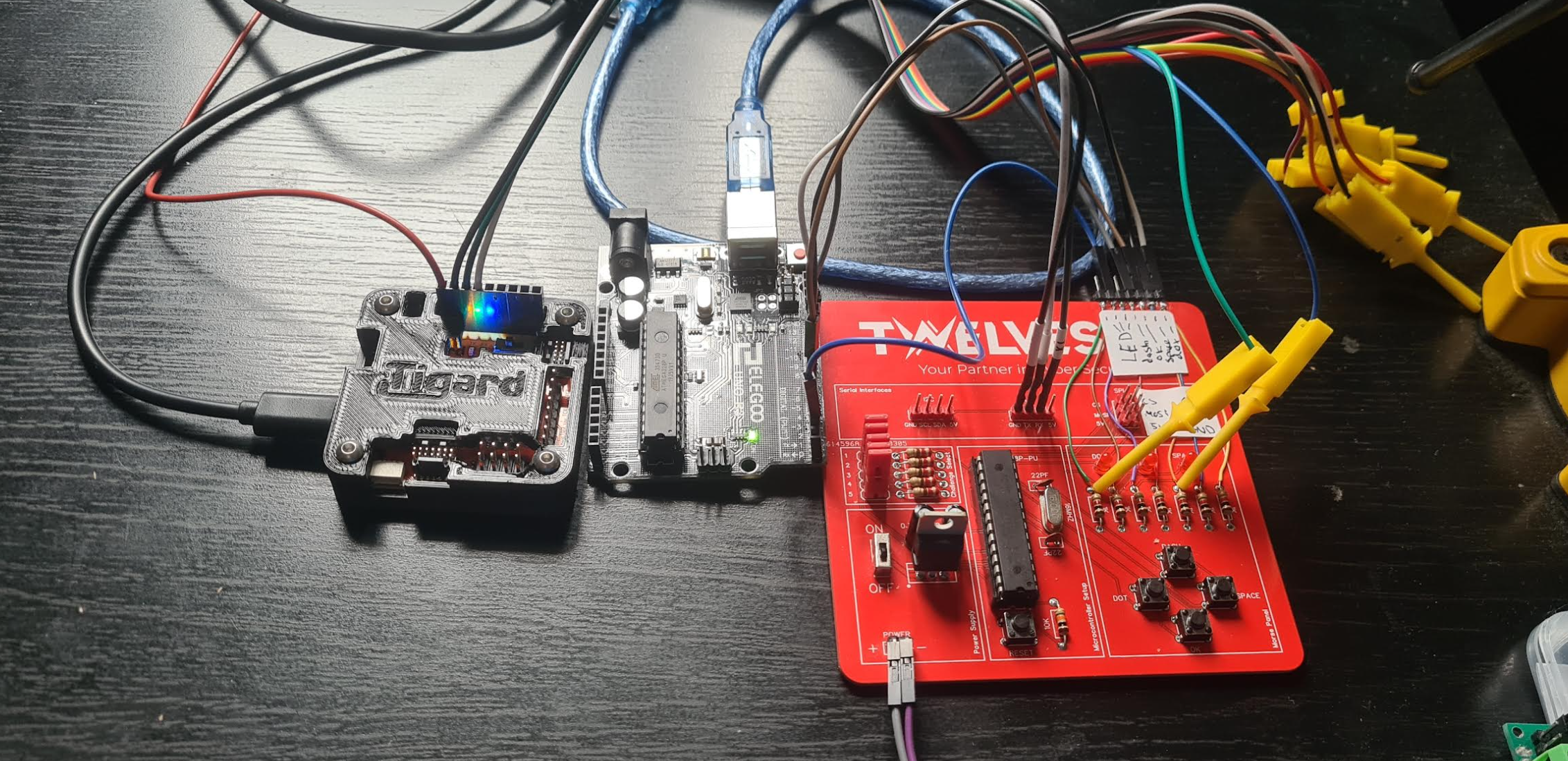
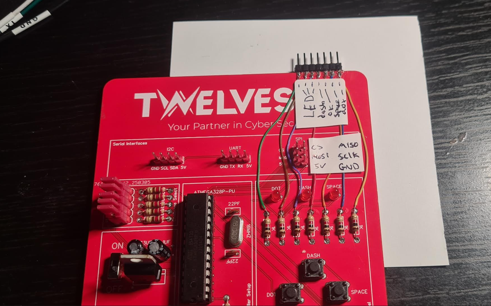
I decided to add some header pins from the resistors (LEDs and buttons) for easier debugging:
The LED flashed once the first incorrect pin was found, there was a small delay between each pin check, thereby we could dissern each pin one after the other. e.g.:
| pin attempt | time | notes |
|---|---|---|
| 1xxx | 005ms | |
| 2xxx | 010ms | "2" must be correct as took longest |
| 3xxx | 050ms | |
| 21xx | 015ms | "21" took longest of 2nd digit choices |
| 22xx | 010ms | |
| 23xx | 010ms |
... and so on until the code is worked out.
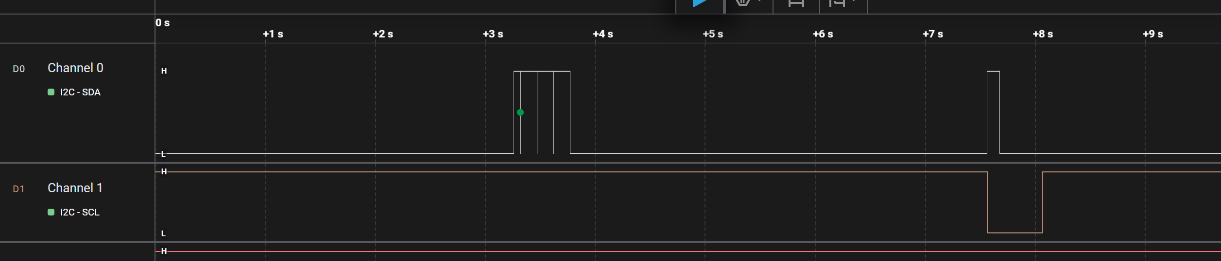
I hooked up the logic analyser to the ok button and the LED. The LED on the lower trace:
So I didnt have to push the buttons manually (because that would have been a disaster) I wired up the arduino to the buttons and LED and created an arduino sketch to ineract with input and output pins and time when pins go high/low: 09_arduino.ino
I also created a python class to talk to the arduino: arduinIO.py
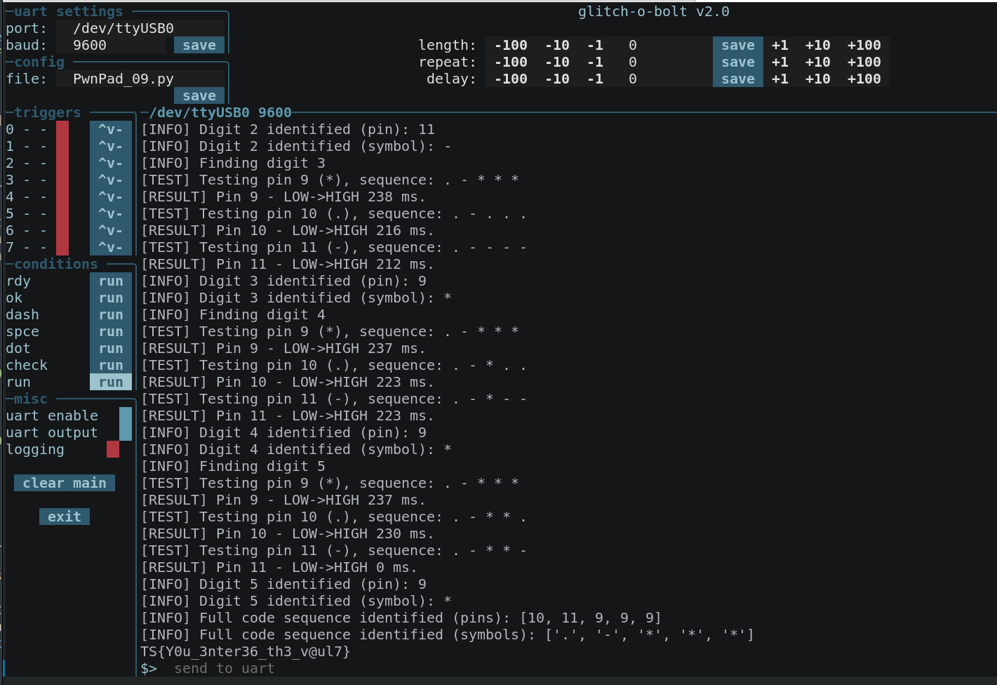
This was all tied together with of course, a glitch-o-bolt config: 09_GoB_config.py
With the logic analyzer still hooked up it was possible to see the delay buy usign the timing markers on the start of the button press and the start of the LED turning off:
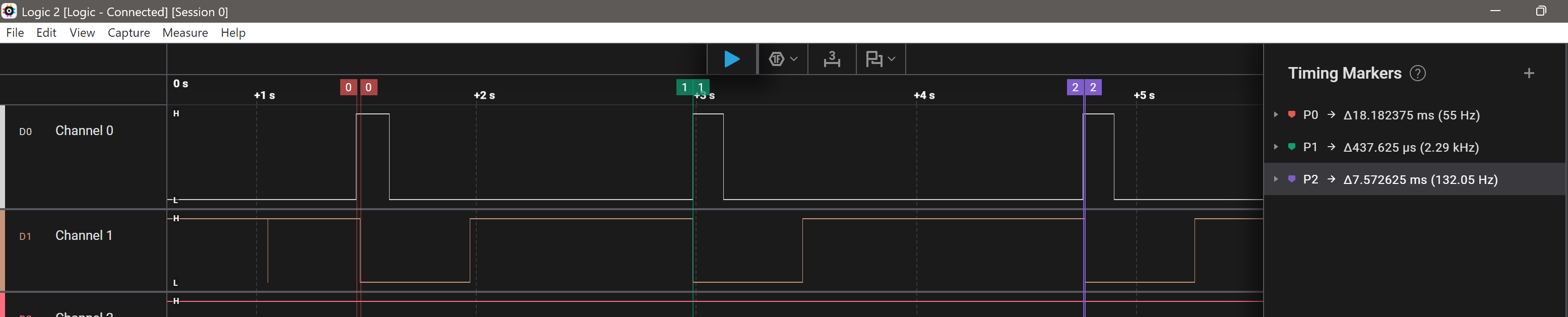
This demonstrates the time between ".", "-" and " " (symbolized as "*") for identifying the first character
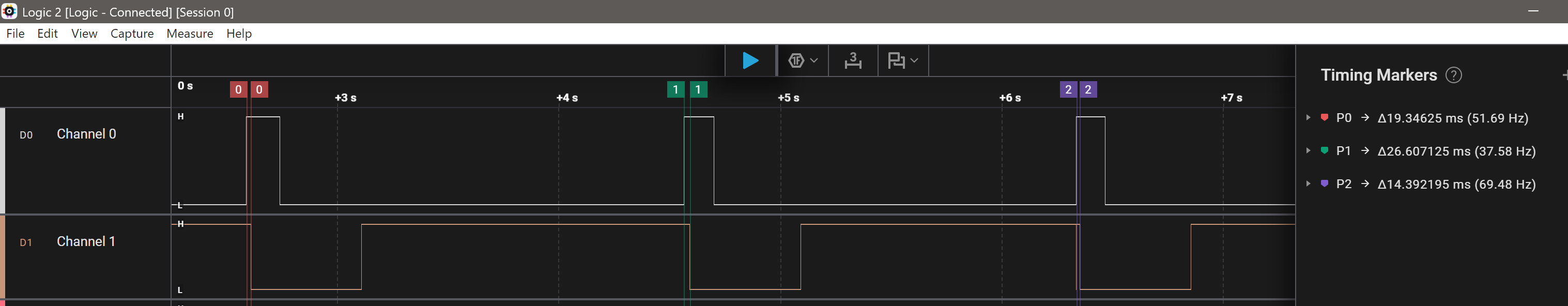
The second char
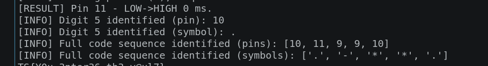
And of course the glitch-o-bolt solution: