Yup, another little weekend electronics kit. As the title suggests, this time I’m making an oscilloscope.
For those that don’t know what that is, ripped directly from google:
“An oscilloscope is a laboratory instrument commonly used to display and analyze the waveform of electronic signals. In effect, the device draws a graph of the instantaneous signal voltage as a function of time.”
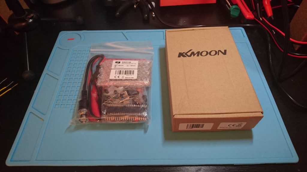
Here’s how it came packaged, followed by the tedious process of how I unpacked and set out the contents:
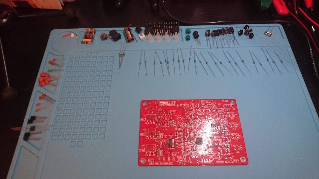
Damn that’s a lot of resistors! The guide was pretty simple, much like the last kit. Find the part, match it’s number to the number on the PCB and solder it in. The resistors were a little bit harder than last time, these were 5 band colour coded, and boy is it easy to mess these up! So I went through manually trying to read the colour codes with help from an app, and eventually got to step 2.
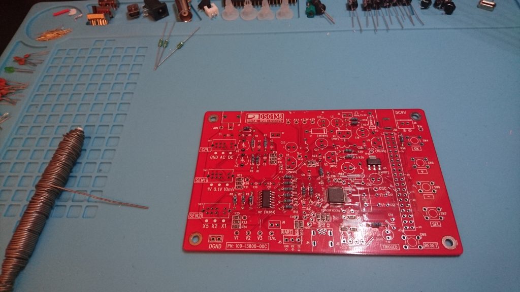
Step 2 – Everything else!
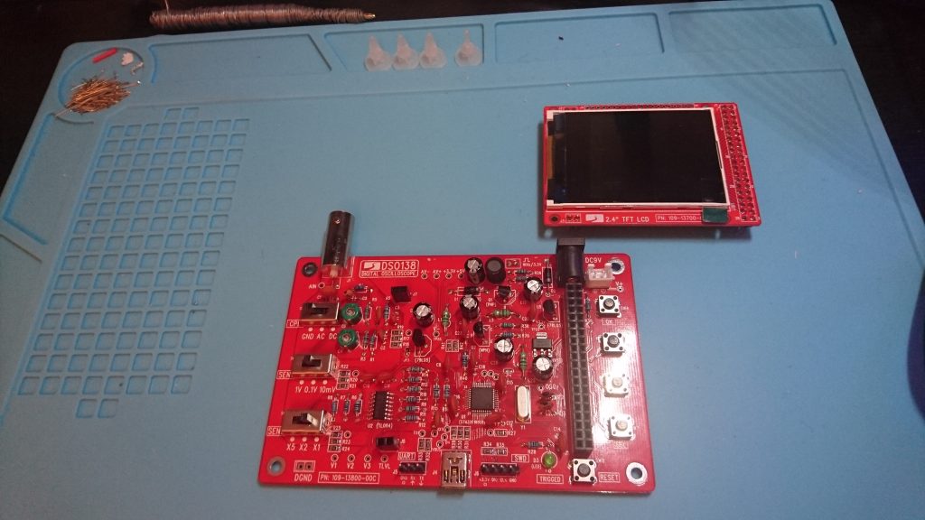
I put the screen on, add some power and get the boot screen, everything is looking good. Try to get a signal from the on-board square wave generator – nothing! damn… in fact the line isn’t moving at all, weather I hold the clip, change switch settings, nothing!
I Take it apart again, manually test every resistor with a multimeter (find 2 that need swapping) double check all the solder points and add more where it seems like it might be needed. Then time for take 2.
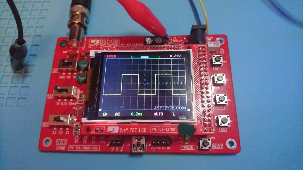
YES it works! I go through the calibration steps to tidy up the signal as best I can…
Now time for the case. This is what I unbox:
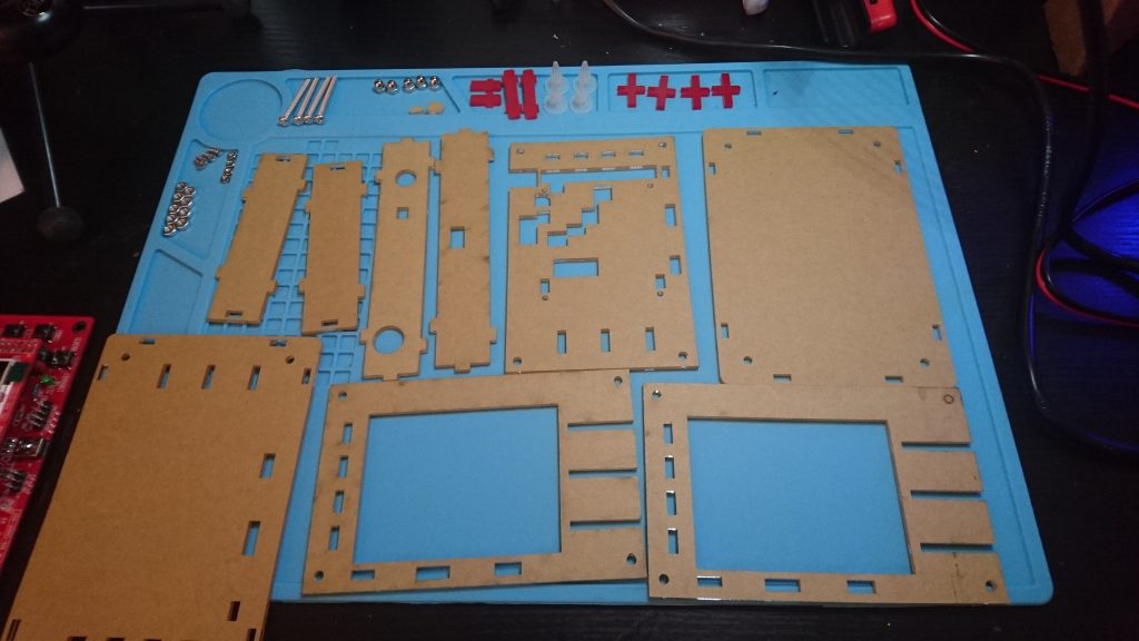
Lovely! a maze of plastic to somehow assemble into a case for this odd shaped thing. Well I’ve got this far how hard can it be. Lets start by removing all the paper stuck to it.
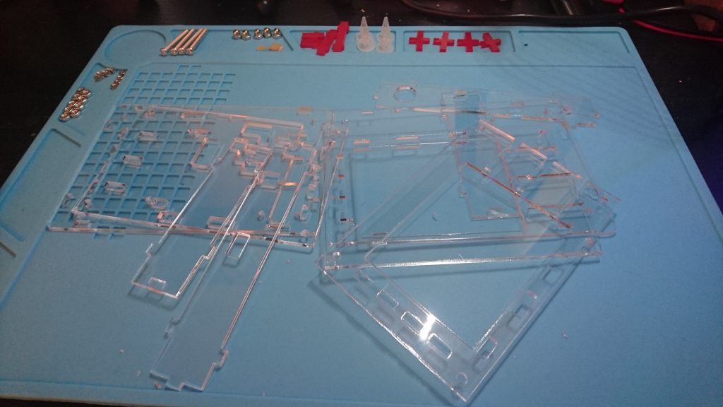
Oh great.. yea that makes things easier! I’m starting to really hate these plastic mensa-puzzle case kits! – After trying to balance the pieces into various box shapes I head for youtube and follow along someones tutorial.
Even they got it wrong and it needed undoing and rebuilding half way through!
In total this case was put together then taken apart and re-put together 4 times!
It was totally worth it!
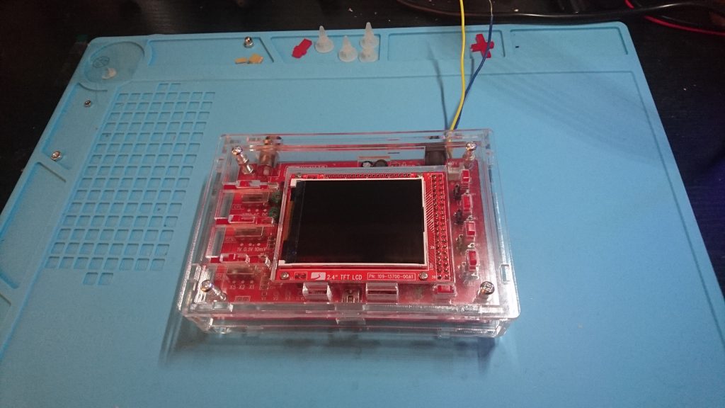
I did use the same wire to hookup to underneath the barrel jack like last time, and yea I did end up using the soldering iron to melt the plastic to allow it through.
It’s time for the moment of truth, lets power it on…
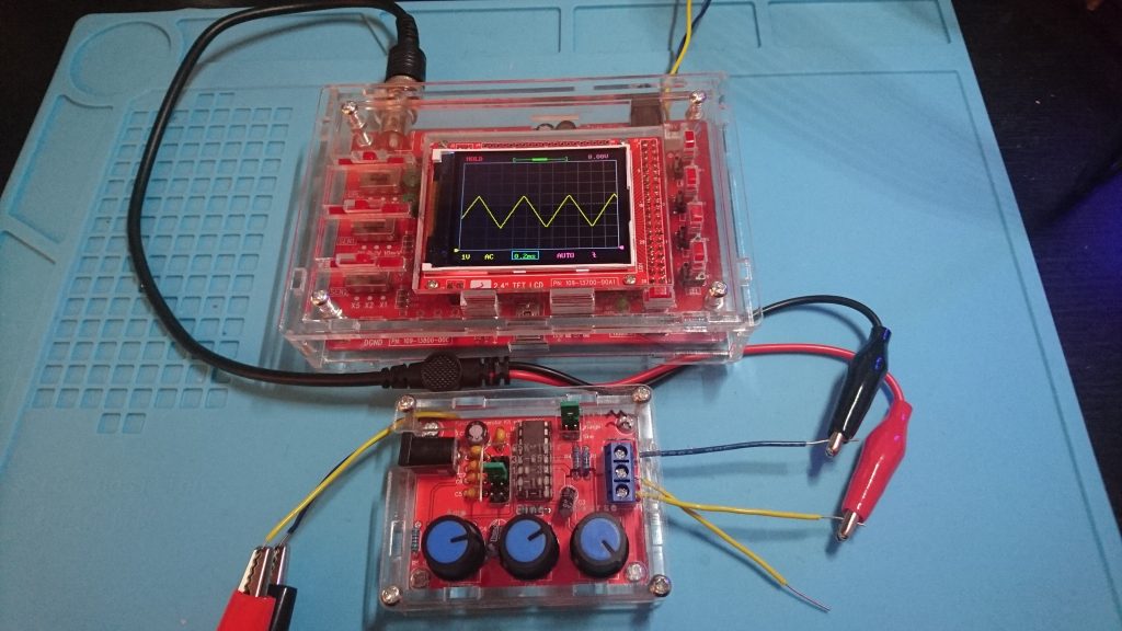
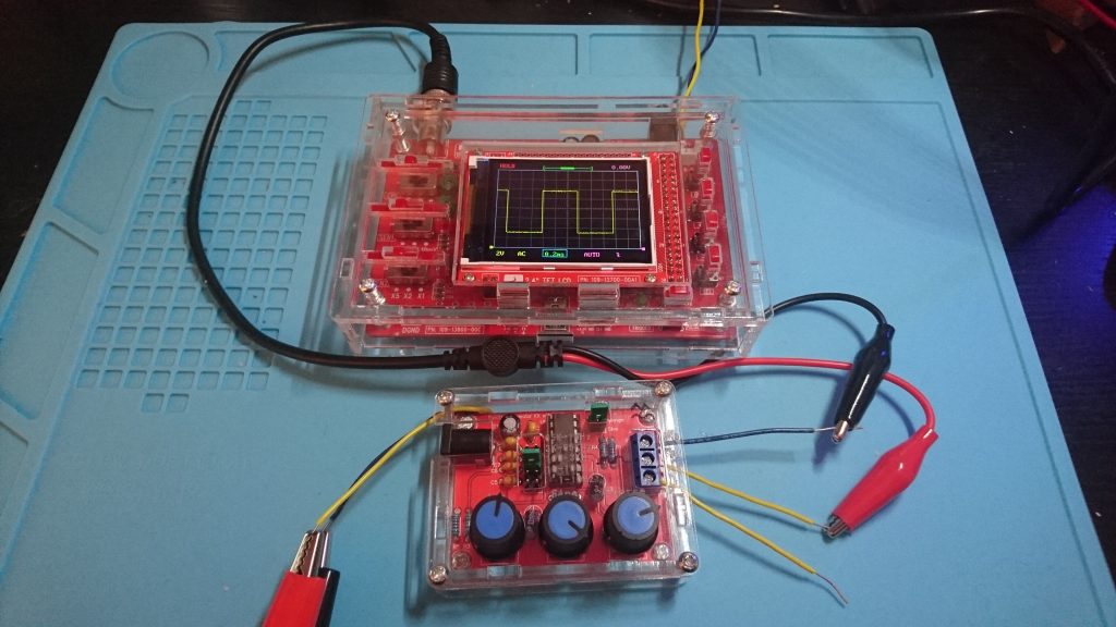
It worked! w00p… Here’s some pics of it picking up signals from last weeks signal generator:
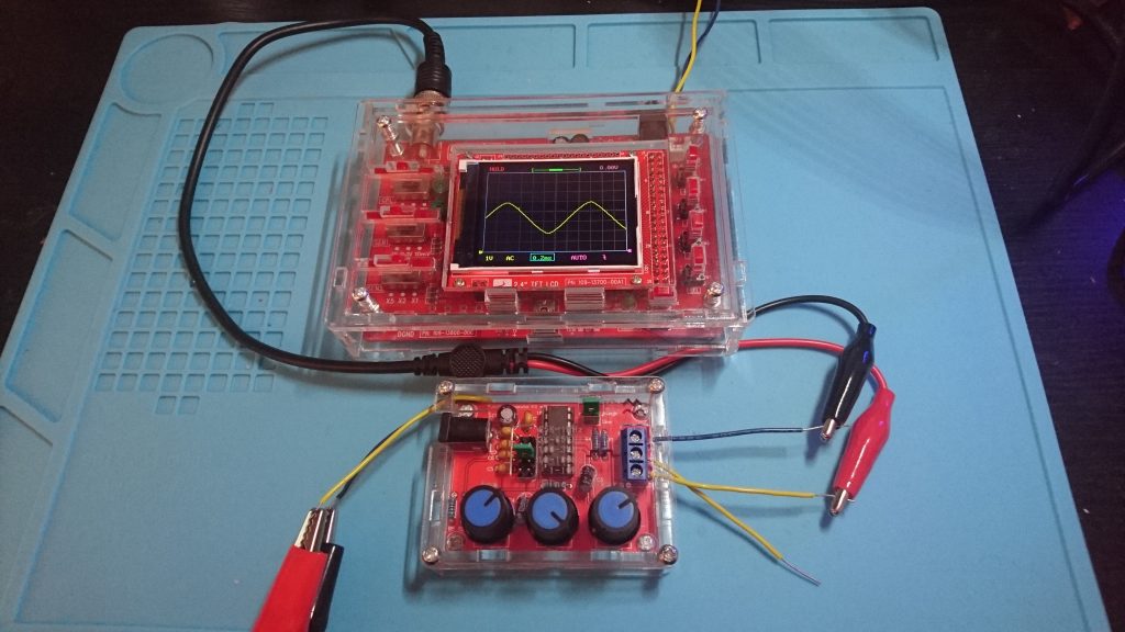
All in all, it was a total nightmare to build! But worth it, having something that works that is handmade is awesome. I’d recommend anyone getting this kit and giving it a go, it’s fairly cheap, I think £15 on amazon. If I can build it I’m pretty sure anyone can.
Advice: Test each resistor with a multimeter before putting on the board – don’t trust the colour bands!
I lost Page 2 of the guide (which contains how to calibrate and use the device) – it’s available online, definitely read that. It’s not quite ready to play once it’s built and needs a little tweaking, also there’s tips and tricks to make it do stuff with button combinations etc.
Here’s to another successful electronics kit build.
