So this’ll just be a quick blog on my Saturday project. As the title suggests I built a signal generator kit.
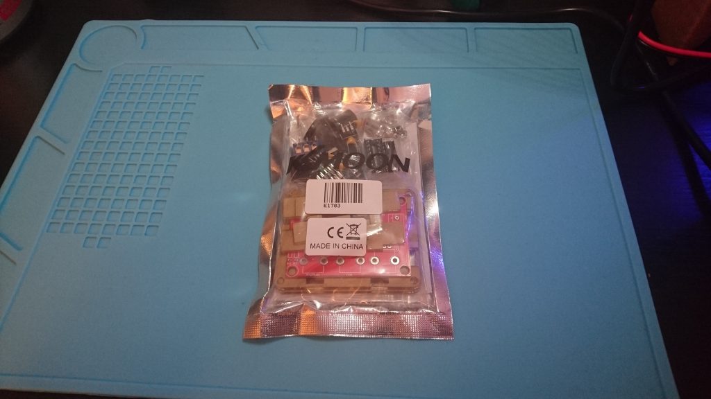
It came packaged like this:
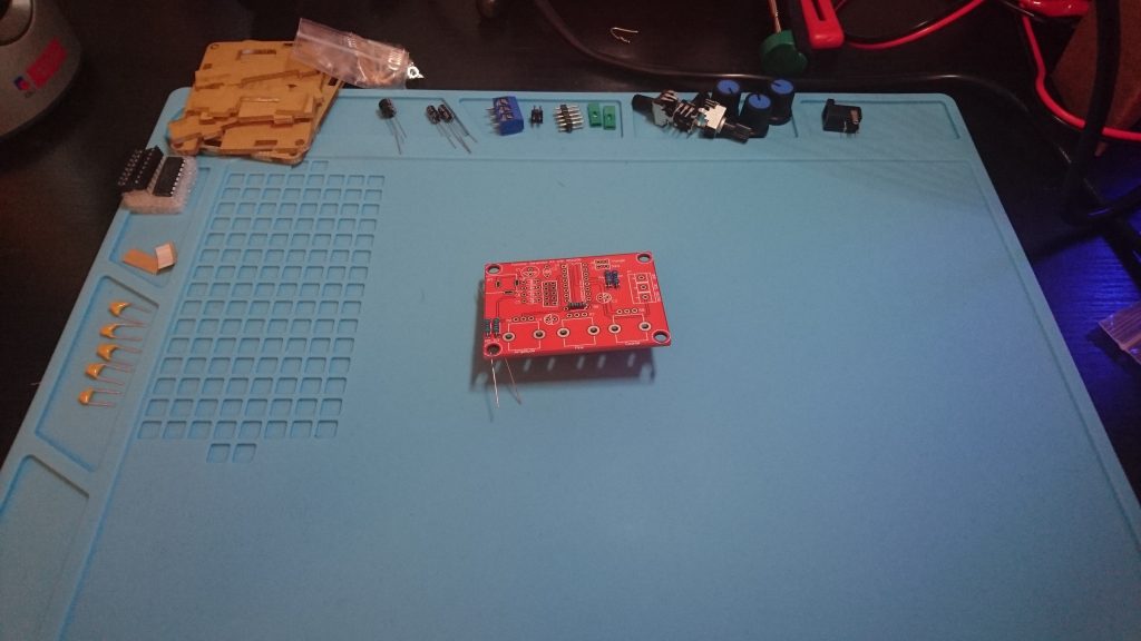
I decided the best thing to do was to split all the components out and tidy the work area ready for putting it together:
The instructions were fairly simple. It would have the item number/code then what the item should be… eg.
R1 = 1k Resistor
It was then just a case of finding the 1k resistor and “R1” on the PCB and soldering it in place.
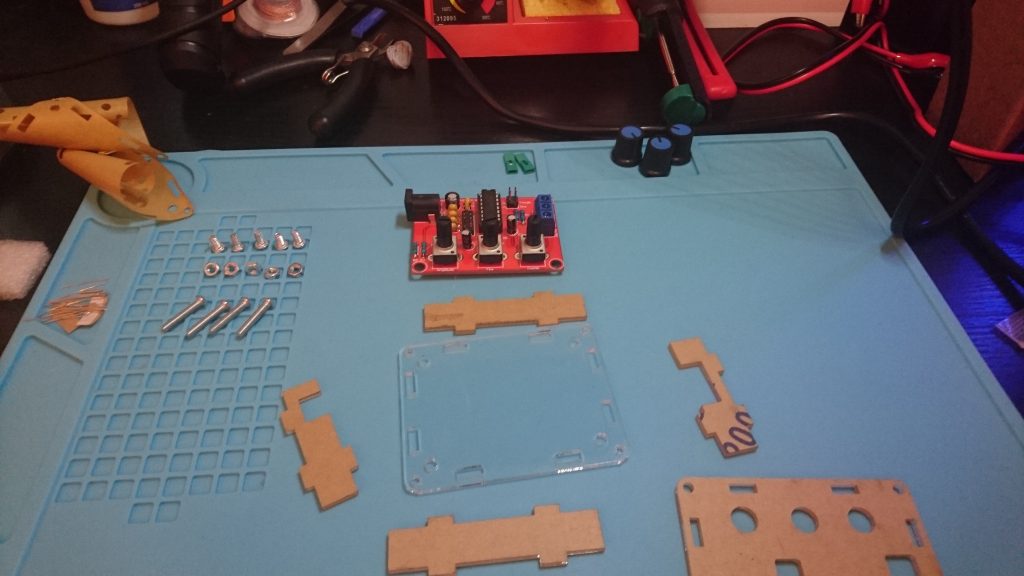
Very quickly I was left with the following, and time to assemble the case:
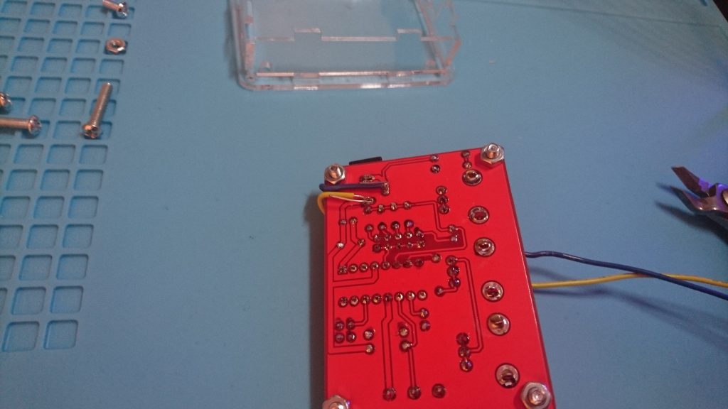
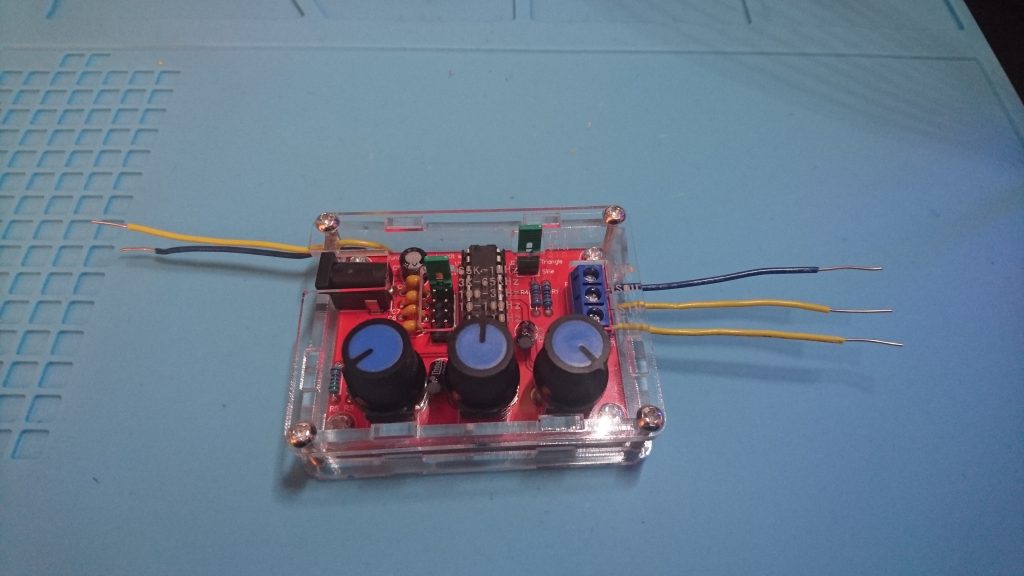
I then realised I didn’t want to use it’s on-board socket to power it so decided to add some wires to where the socket was soldered on and modify the case a little to allow these wires through (by melting the case with the soldering iron)
The case was then assembled and knob heads put on. Here’s the finished product:
So that was pretty easy to build, but I still had no idea if it works. I don’t have an oscilloscope, however do have a cheap logic analyser and figured that would be able to do the job, so rigged that up never having used it before:
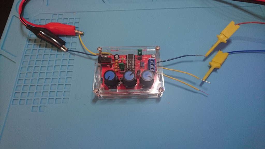
Low and behold it works… sort of.
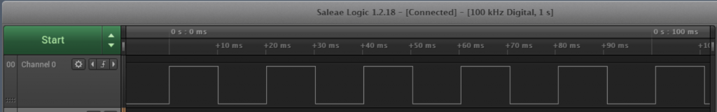
The Saleae logic software is super easy to use, a couple of mins playing around and someone even slightly tech savvy will be able to pick it up. However it turns out it can only do digital and not analog, so it’s possible to read the square wave functions, but not the sine or triangle waves.
As for proving that it works, I think I would call this a success. And I’m glad I finally got to play with the logic analyser and work out how that functions.
After playing for a little bit I was able to change the jumpers and adjust the knobs to make the square wave what I wanted.
here’s screenshots of it at: 10ms delay @ 50Hz and 1ms delay @ 500Hz

I’m not sure if this helped anyone or is even interesting, but I had fun building it.
