I wanted to give a quick demo on how to reverse engineer an ATtiny85 micro-controller to read the code stored on the device. For this demo the “hello world” is a small circuit with four buttons. By typing in the correct code a green LED will flash, otherwise a red one. (see demo video below)
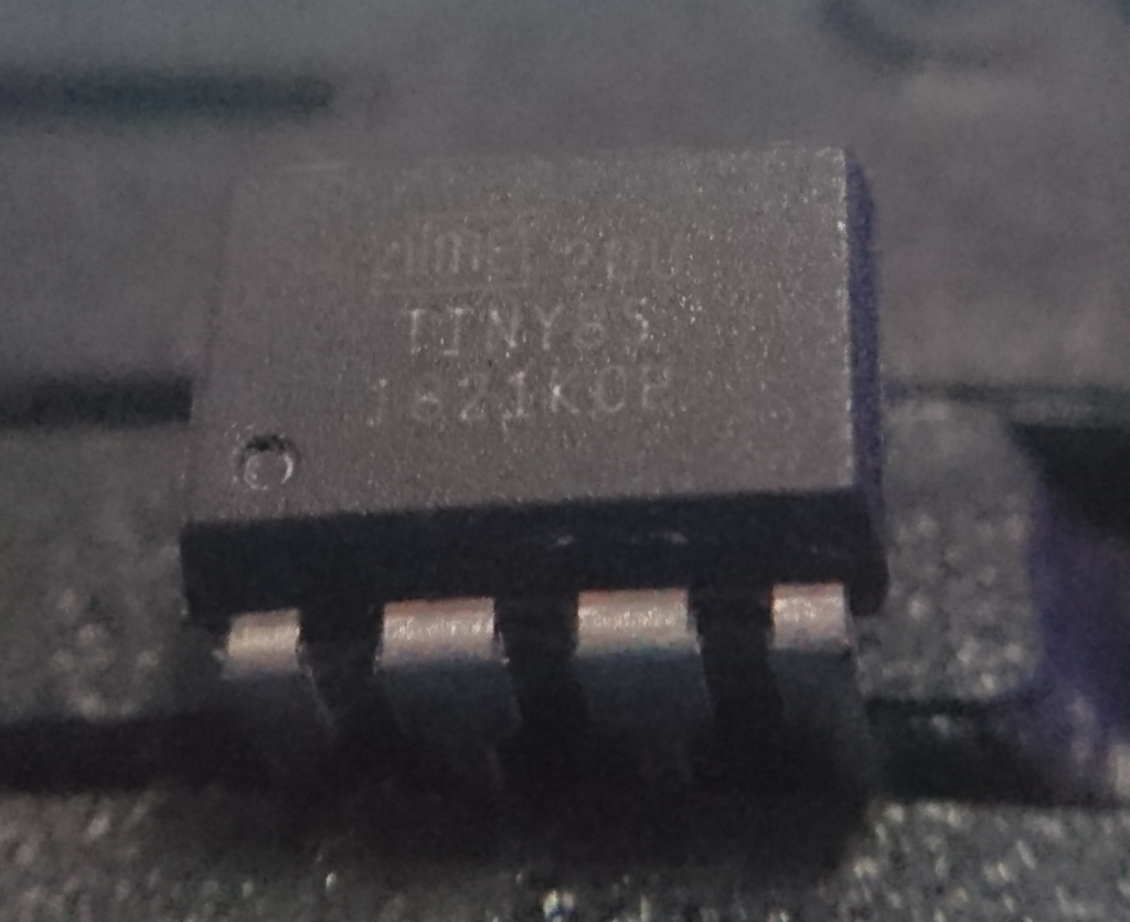
The first thing you will want to do is identify the chip that you want to reverse, usually you can read this from the chip directly:
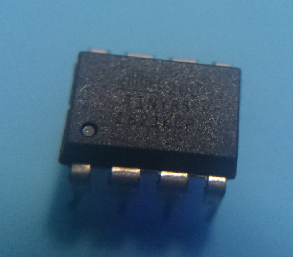
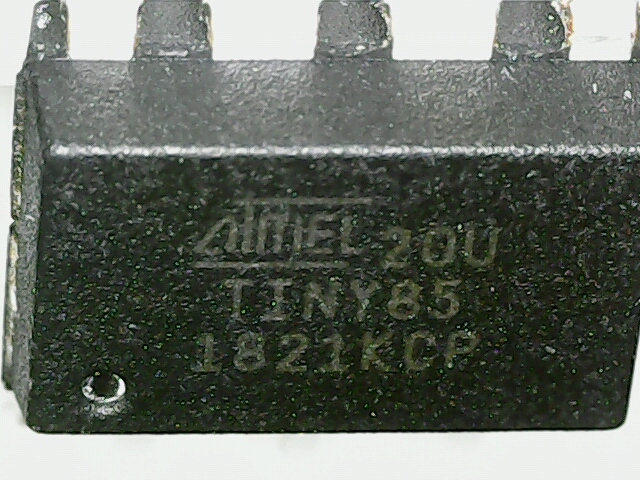
However if you are unable to read this it may help to rub chalk on the chip which will stick in the grooves and contrast against the black plastic:
A cheap microscope helps (amazon link)
Once the chip has been identified it’s time to hunt for documentation to see how it is programmed / interfaced with. For the ATtiny85 this was found to be via SPI.
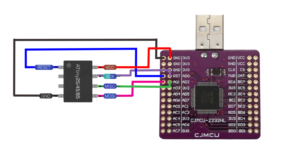
For reversing this we will be using the FT2232HL, a really cheap USB module that can speak most interface “languages” (UART, FIFO, SPI, I2C, JTAG & RS232) https://www.amazon.co.uk/gp/product/B0762DBSDY/
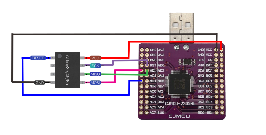
You will need to read the FT2232HL documentation to identify the corresponding pins to attach these together, my initial plan looked as follows:
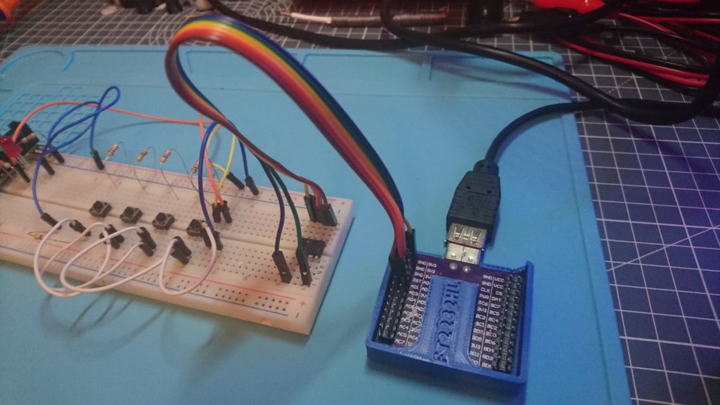
After hooking it all up it looked like:
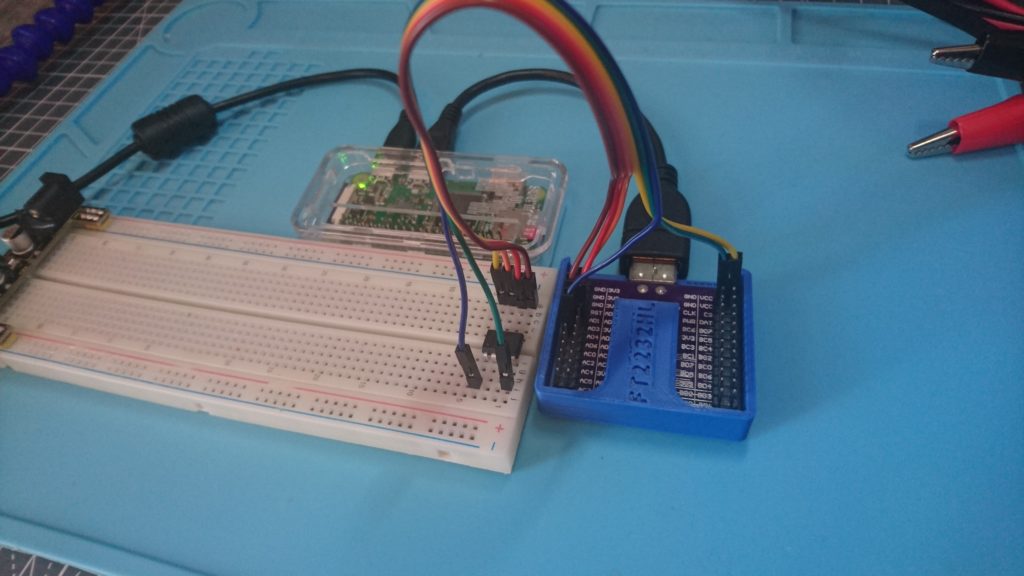
I was trying to get this working using avrdude on windows. This turned out to be more hassle than it was worth and I never got it working. I was warned against trying to use it in a VM, this also proved to be true and did not work. In the end I hooked it up to a raspberry pi zero with a fresh install of raspbian.
This however was still not working! after much head scratching and -vvvv flag on avrdude I noticed various errors along the lines of:
D set_pin(243): Setting pin 3 (ADBUS3) as RESET: high (high active) |
It was obvious then that I had some of the pins connected wrong as per the example above “reset” had to go to “AD3” instead of “RST”. After changing these the schematic then looked like:
And physically:
The command finally works!
root@raspberrypi:/home/pi# avrdude -p attiny85 -P /dev/ttyUSB1 -c 2232HIO -U flash:r:flash.bin:r -b 19200avrdude: AVR device initialized and ready to accept instructionsReading | ################################################## | 100% 0.02savrdude: Device signature = 0x1e930b (probably t85)avrdude: reading flash memory:Reading | ################################################## | 100% 13.86savrdude: writing output file "flash.bin"avrdude: safemode: Fuses OK (E:FF, H:DF, L:E2)avrdude done. Thank you. |
So what do those flags mean?
-p attiny85 = The chip we are wanting to read/write
-P /dev/ttyUSB1 = The port the device is on
-c 2232HIO = The programmer we are using, the code for FT2232HL is 2232HIO
-U flash:r:flash.bin:r = The operation we want to perform, this one means write the flash to flash.bin. Others can be used to pull device info or write new contents to the chip!
-b 19200 = The baud rate the chip uses (not strictly necessary as overrides default)
Now you have the .bin file you an do all the typical reverse engineering things, binwalk, IDA, OllyDBG etc.
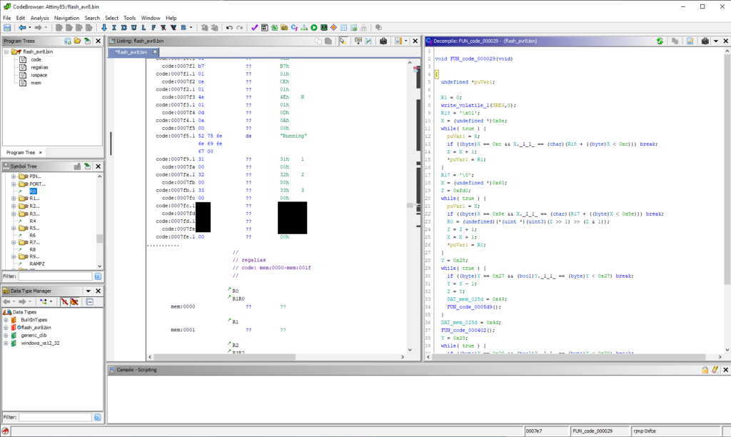
Here’s it in ghidra:
This code being as simple as it is the passcode can also be found by running “strings” against flash.bin:
root@raspberrypi:/home/pi# strings flash.bint/rpA/_?O/s3' h1P'_3@ 11(^3@/01&[3@"31"P1 9N__O$._?O"P1a,q,APP@Running-snip- |
If you would like to try to find the passcode you can download flash.bin here:

I’d like to give a massive thank you to Deral Heiland @Percent_X for helping me get into hardware hacking and writing some awesome blog posts on the subject.
