This blog I’ll demonstrate how I made a prototype product in a weekend, the project “wakeup glasses” is a bit of a joke and a bit crap, but just a little bit of fun. The takeaway here isn’t the end product but more how to get there. Hopefully it will show how easy it is to create something in a short amount of time, and you might learn some tips or tricks in doing so.
So what IS “Wakeup Glasses”?… I ordered some 1w high powered LED’s, the kind used in flood lights or traffic lights and I already had some gyroscope/accelerometer modules. Squash the two together and stick to the side of some glasses (dangerously close to your eye) and whenever your head tilts beyond a specific angle the LED turns on waking the user up! (hopefully not blinding them)
Here is the end product in action:
Requirements
To start I knew the parts needed (the gyroscope and the LED) and was hoping to use an ATTINY85 rather than an Arduino or Raspberry pi to keep things small and light. I made some quick notes to check there were enough pins and that this was viable:

Breadboarding
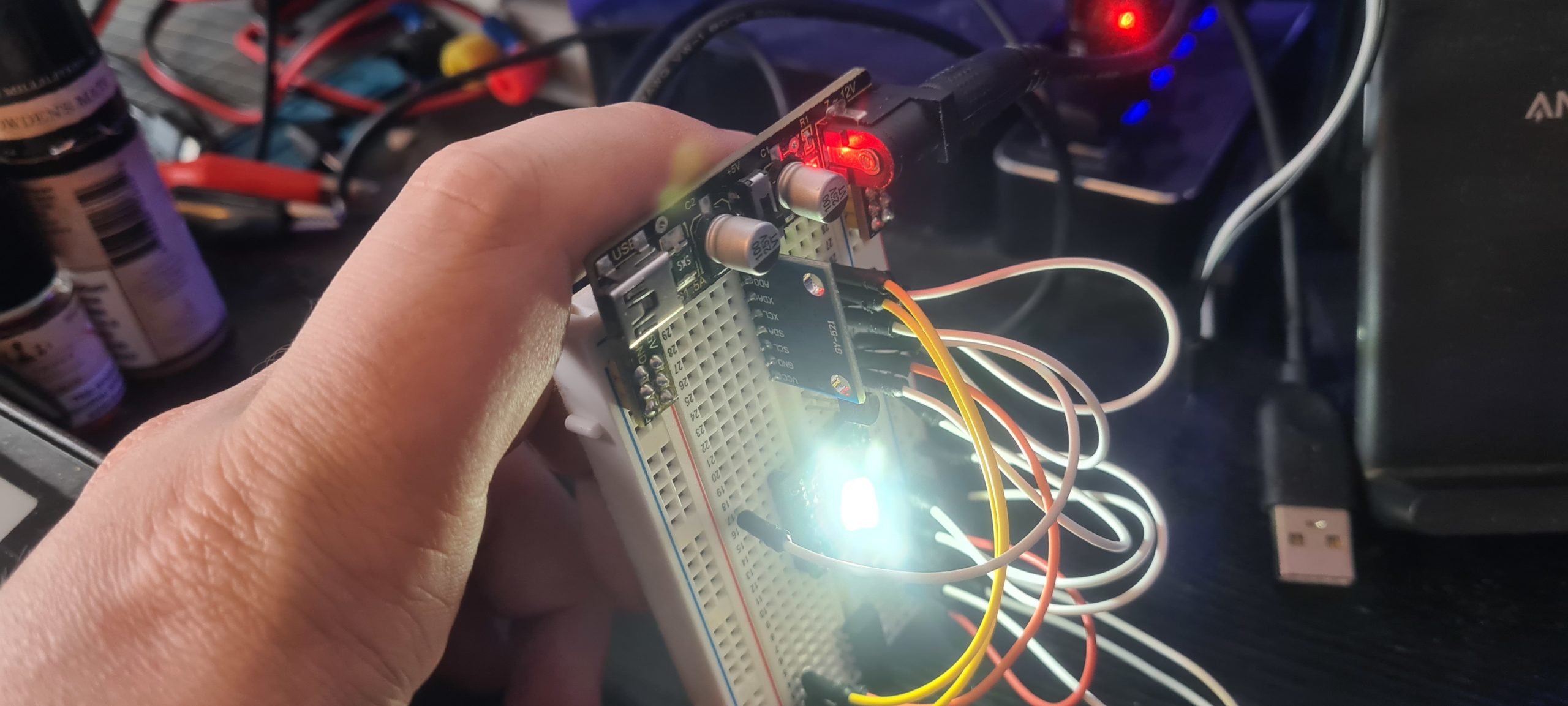
Now the fun part begins, it’s time to get the components onto a breadboard and make a working version of the idea on it. This is where the programming is done and components tested. For me this is a very “trial-and-error” endeavour. For example: The microcontroller didn’t output enough power to turn on the LED, when the LED was reversed so the “-” went to the microcontroller’s pin it wasn’t bright enough, the solution was to use the microcontroller to enable a transistor which in turn allowed power to go directly from the battery through the LED and back into the battery “-“. You don’t need to understand the technical details here, just that this is the time for playing and getting everything working as expected.
This is how this projects breadboard looked near then end:

The code to make this work was as follows:
#include <Arduino.h>#include <SoftwareSerial.h> #include <TinyWireM.h> // serial outputconst int rx=-1;const int tx=4;SoftwareSerial mySerial(rx,tx);// gy-521 accelerometerconst int MPU_addr=0x68; // I2C address of the MPU-6050float AcX,AcY,AcZ,Tmp,GyX,GyY,GyZ;double aZ,DaZ, Gy;double pitch,roll,yaw;float elapsedTime, currentTime, previousTime;float accAngleX, accAngleY, gyroAngleX, gyroAngleY, gyroAngleZ;float AccErrorX, AccErrorY, GyroErrorX, GyroErrorY, GyroErrorZ;char tmp_str[7]; // temporary variable used in convert functionconst int buttonPin = 3;const int ledPin = 1;int c = 0;void setup() { // setup serial pinMode(rx,INPUT); pinMode(tx,OUTPUT); mySerial.begin(9600); mySerial.println(F("Ready")); //setup acelorometer TinyWireM.begin(); mpu_init(); // setup button pinMode(buttonPin, INPUT_PULLUP); // setup LED ledOff();}void loop() { int buttonValue = digitalRead(buttonPin); mpu_read(); if (buttonValue == LOW){ mySerial.print("B: + "); ledOn(); calculate_IMU_error(); }else{ mySerial.print("B: - "); if(pitch > -1.40 ){ ledOn(); }else{ ledOff(); } }// mySerial.print("aX = "); mySerial.print(convert_int16_to_str(AcX));// mySerial.print(" | aY = "); mySerial.print(convert_int16_to_str(AcY));// mySerial.print(" | aZ = "); mySerial.print(convert_int16_to_str(AcZ)); // the following equation was taken from the documentation [MPU-6000/MPU-6050 Register Map and Description, p.30]// mySerial.print(" | tmp = "); mySerial.print(Tmp / 340.00 + 36.53);// mySerial.print(" | gX = "); mySerial.print(convert_int16_to_str(GyX));// mySerial.print(" | gY = "); mySerial.print(convert_int16_to_str(GyY)); //mySerial.print(" | degY = "); mySerial.print(convert_int16_to_str(Gy));// mySerial.print(" | gZ = "); mySerial.print(convert_int16_to_str(GyZ)); mySerial.print(" | r = ");mySerial.print(roll); mySerial.print(" | p = ");mySerial.print(pitch); mySerial.print(" | y = ");mySerial.print(yaw); mySerial.println(); //delay(200); }char* convert_int16_to_str(int16_t i) { // converts int16 to string. Moreover, resulting strings will have the same length in the debug monitor. sprintf(tmp_str, "%6d", i); return tmp_str;}void mpu_init() { TinyWireM.beginTransmission(MPU_addr); TinyWireM.send(0x6B); // PWR_MGMT_1 register TinyWireM.send(0); // set to zero (wakes up the MPU-6050) TinyWireM.endTransmission();}void mpu_read() { TinyWireM.beginTransmission(MPU_addr); TinyWireM.send(0x3B); // starting with register 0x3B (ACCEL_XOUT_H) TinyWireM.endTransmission(); TinyWireM.requestFrom(MPU_addr, 14); // request a total of 14 registers AcX=(TinyWireM.receive()<<8|TinyWireM.receive()) / 16384.0; // 0x3B (ACCEL_XOUT_H) & 0x3C (ACCEL_XOUT_L) AcY=(TinyWireM.receive()<<8|TinyWireM.receive()) / 16384.0; // 0x3D (ACCEL_YOUT_H) & 0x3E (ACCEL_YOUT_L) AcZ=(TinyWireM.receive()<<8|TinyWireM.receive()) / 16384.0; // 0x3F (ACCEL_ZOUT_H) & 0x40 (ACCEL_ZOUT_L) Tmp=TinyWireM.receive()<<8|TinyWireM.receive(); // 0x41 (TEMP_OUT_H) & 0x42 (TEMP_OUT_L) GyX=(TinyWireM.receive()<<8|TinyWireM.receive()) / 131.0; // 0x43 (GYRO_XOUT_H) & 0x44 (GYRO_XOUT_L) GyY=(TinyWireM.receive()<<8|TinyWireM.receive()) / 131.0; // 0x45 (GYRO_YOUT_H) & 0x46 (GYRO_YOUT_L) GyZ=(TinyWireM.receive()<<8|TinyWireM.receive()) / 131.0; // 0x47 (GYRO_ZOUT_H) & 0x48 (GYRO_ZOUT_L) GyX = GyX - GyroErrorX; GyY = GyY - GyroErrorY; GyZ = GyZ - GyroErrorZ; // Calculating Roll,Pitch adn yaw from the accelerometer data accAngleX = (atan(AcY / sqrt(pow(AcX, 2) + pow(AcZ, 2))) * 180 / PI) - 0.58; // AccErrorX ~(0.58) See the calculate_IMU_error()custom function for more details accAngleY = (atan(-1 * AcX / sqrt(pow(AcY, 2) + pow(AcZ, 2))) * 180 / PI) + 1.58; // AccErrorY ~(-1.58) gyroAngleX = gyroAngleX + GyX * elapsedTime; // deg/s * s = deg gyroAngleY = gyroAngleY + GyY * elapsedTime; //yaw = yaw + GyZ * elapsedTime; roll = 0.96 * gyroAngleX + 0.04 * accAngleX; pitch = 0.96 * gyroAngleY + 0.04 * accAngleY; }void calculate_IMU_error(){ while (c < 200) { TinyWireM.beginTransmission(MPU_addr); TinyWireM.send(0x3B); TinyWireM.endTransmission(false); TinyWireM.requestFrom(MPU_addr, 6); AcX = (TinyWireM.receive() << 8 | TinyWireM.receive()) / 16384.0 ; AcY = (TinyWireM.receive() << 8 | TinyWireM.receive()) / 16384.0 ; AcZ = (TinyWireM.receive() << 8 | TinyWireM.receive()) / 16384.0 ; // Sum all readings AccErrorX = AccErrorX + ((atan((AcY) / sqrt(pow((AcX), 2) + pow((AcZ), 2))) * 180 / PI)); AccErrorY = AccErrorY + ((atan(-1 * (AcX) / sqrt(pow((AcY), 2) + pow((AcZ), 2))) * 180 / PI)); c++; } //Divide the sum by 200 to get the error value AccErrorX = AccErrorX / 200; AccErrorY = AccErrorY / 200; c = 0; // Read gyro values 200 times while (c < 200) { TinyWireM.beginTransmission(MPU_addr); TinyWireM.send(0x43); TinyWireM.endTransmission(false); TinyWireM.requestFrom(MPU_addr, 6); GyX = TinyWireM.receive() << 8 | TinyWireM.receive(); GyY = TinyWireM.receive() << 8 | TinyWireM.receive(); GyZ = TinyWireM.receive() << 8 | TinyWireM.receive(); // Sum all readings GyroErrorX = GyroErrorX + (GyX / 131.0); GyroErrorY = GyroErrorY + (GyY / 131.0); GyroErrorZ = GyroErrorZ + (GyZ / 131.0); c++; } //Divide the sum by 200 to get the error value GyroErrorX = GyroErrorX / 200; GyroErrorY = GyroErrorY / 200; GyroErrorZ = GyroErrorZ / 200; // Print the error values on the Serial Monitor /*mySerial.print("AcErrX: "); mySerial.println(AccErrorX); mySerial.print("AcErrY: "); mySerial.println(AccErrorY); mySerial.print("GyErrX: "); mySerial.println(GyroErrorX); mySerial.print("GyErrY: "); mySerial.println(GyroErrorY);*/ mySerial.print("GyErrZ: "); mySerial.println(GyroErrorZ);}void ledOff(){ pinMode(ledPin, OUTPUT); //off digitalWrite(ledPin, LOW); //Set the LED pins to HIGH. This gives power to the LED and turns it on}void ledOn(){ pinMode(ledPin, OUTPUT); //red digitalWrite(ledPin, HIGH); // Set the LED pins to LOW. This turns it off} |
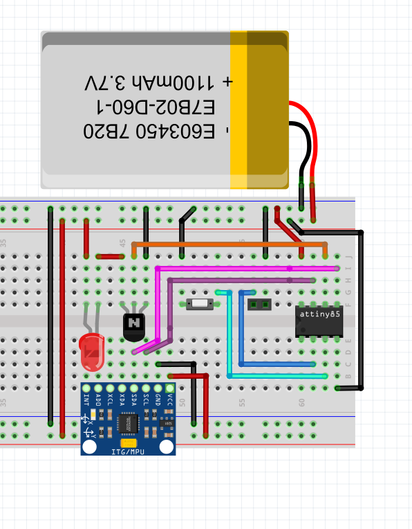
Once this is in a functional state I HIGHLY recommend replicating this in imaging software to have a version that is easy to read for future reference. This turned out as follows:
PCB
This step was skipped for this project as I planned to just solder the wires up and squash it in the case held in place with stands in the case and hot glue.
If it is a one-off project you could get away with soldering and wiring up the components on “perf-board” and not need to make a custom PCB.
If you are wanting a custom PCB there are plenty of ways to quickly manufacture them at home from printing onto transfer paper and using chemicals on the copper blank to my go-to of CNC milling the copper blank.
Either way you will want to create your PCB layout in software of choice (I use KiCAD mostly or sometimes EasyEDA) create it in copper and populate it’s components. My guide on this
Housing / Case
Using “Fusion 360” you should create your case for the project. Generally this is a simple box with holes for IO such as a screen, USB port. headphones socket, antenna hole etc. This project was going to go on the side of a pair of glasses so consideration was taken to make a ridge to place the glasses in. I like to create all the components first and lay them out how I would like the to fit before creating the case around them. In Fusion 360 this project turned out as follows with the transparent area being the case to 3D print:
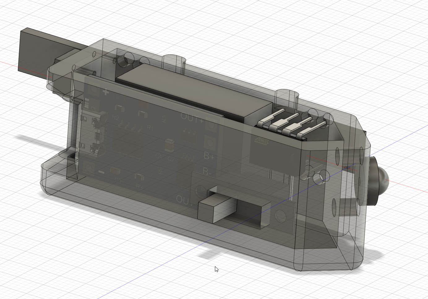
It turns out there was a couple of issues with this design.
1) I forgot to add the gyroscope module
2) There’s not enough space left for wiring.
Luckily there was enough room to squeeze the gyroscope module in. As for the wiring I could have used less when soldering it all together, OR made the case with more room allowed for it.
Conclusion
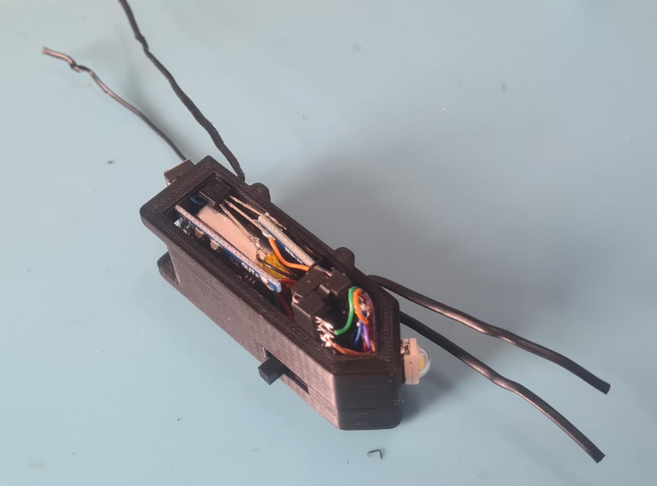
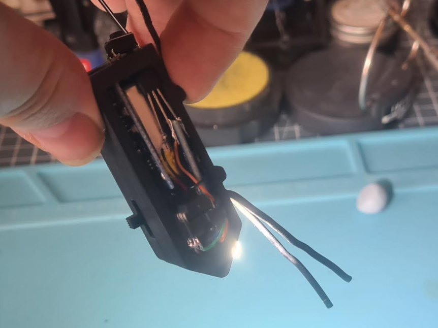
Now you should have the case, PCB and all components ready to create the product. This is how this project looked all wired up before being put into the case:
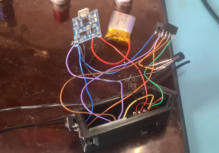
It generally doesn’t look this messy if using a PCB!
once it’s all together you should have a finished prototype (see video at beginning of post)
You now have a working prototype! From here you can refine the design, go back to any step and modify what’s nessesecary. If you feel it is ready you could go on to production. For PCB’s I’d recommend “JLC PCB” I’ve had good experiences using them in the past, they do cheap PCB’s however they take a while to get delivered unless you pay for premium delivery. I’d also recommend uploading your 3D case model to thingiverse to allow other people to print the case and modify it to fit their own needs.
I hope this post helped in some way, maybe helped you get a better understanding of the process of making things or just tips?
If you have any questions feel free to leave them in the comment section below.
